

CUSTOM U-SHAPED ELECTRIC HEATING ELEMENT
U-Shaped Tubular Heating Element
Custom U-shaped electric tubular heating elements for water, oil, air, tanks, ovens and industrial equipment.
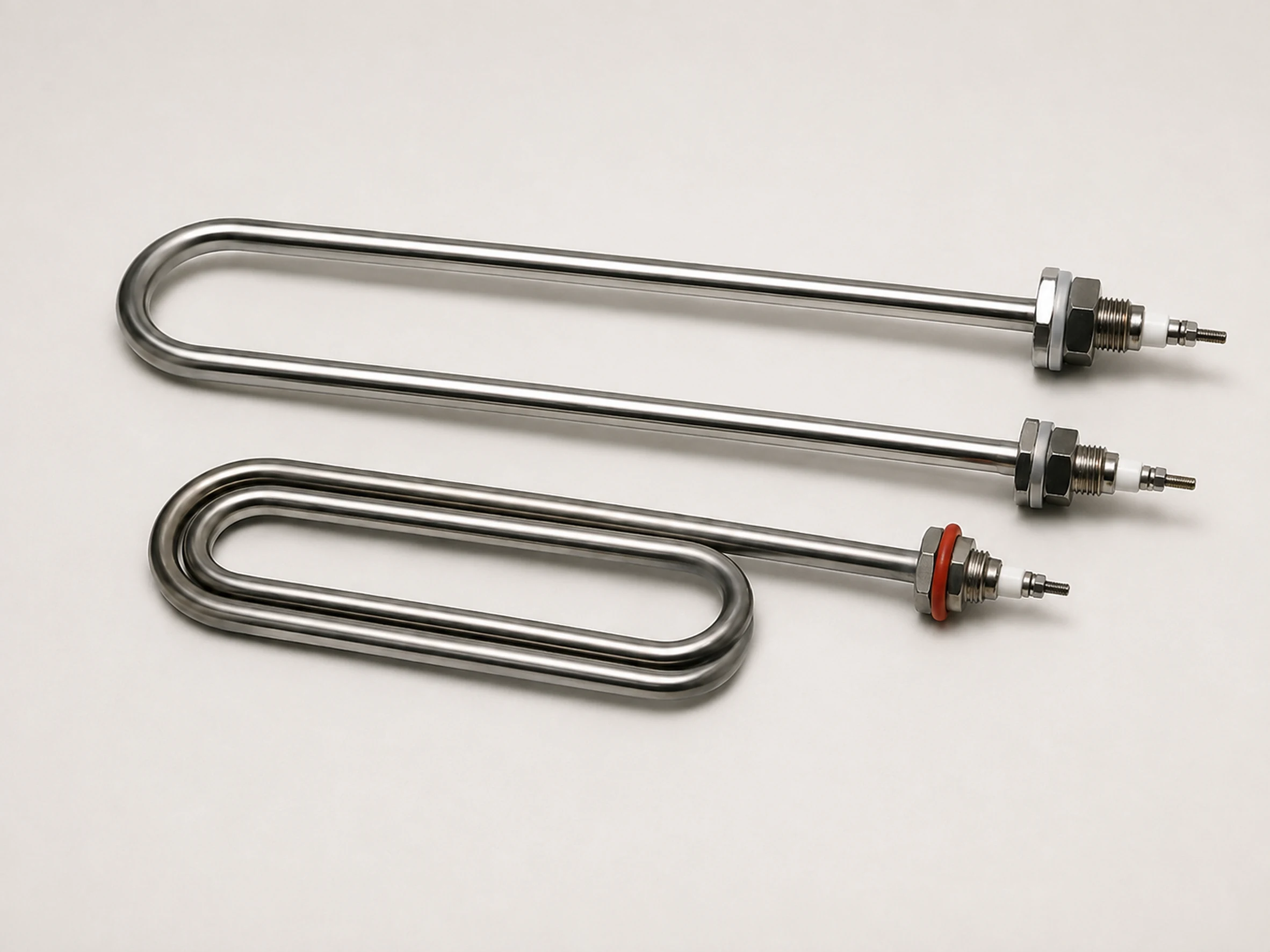
The U-Shaped Tubular Heating Element is a formed electric resistance heater with two parallel legs connected by a U bend. The shape provides a compact heating area and convenient mounting for immersion, air heating, tank heating and equipment integration.
Tube diameter, leg length, center distance, bend radius, voltage, power, watt density, sheath material, cold zones, fittings and terminals can be customized according to the medium and installation drawing. The element can be supplied individually or assembled into flanges, brackets and heater bundles.
Product Overview
The U-Shaped Tubular Heating Element uses the same basic resistance-wire and magnesium-oxide construction as a tubular heater, but is formed into a U shape with two terminal legs. The geometry is widely used where a compact element must enter a tank, vessel, duct, oven or machine through one mounting area.
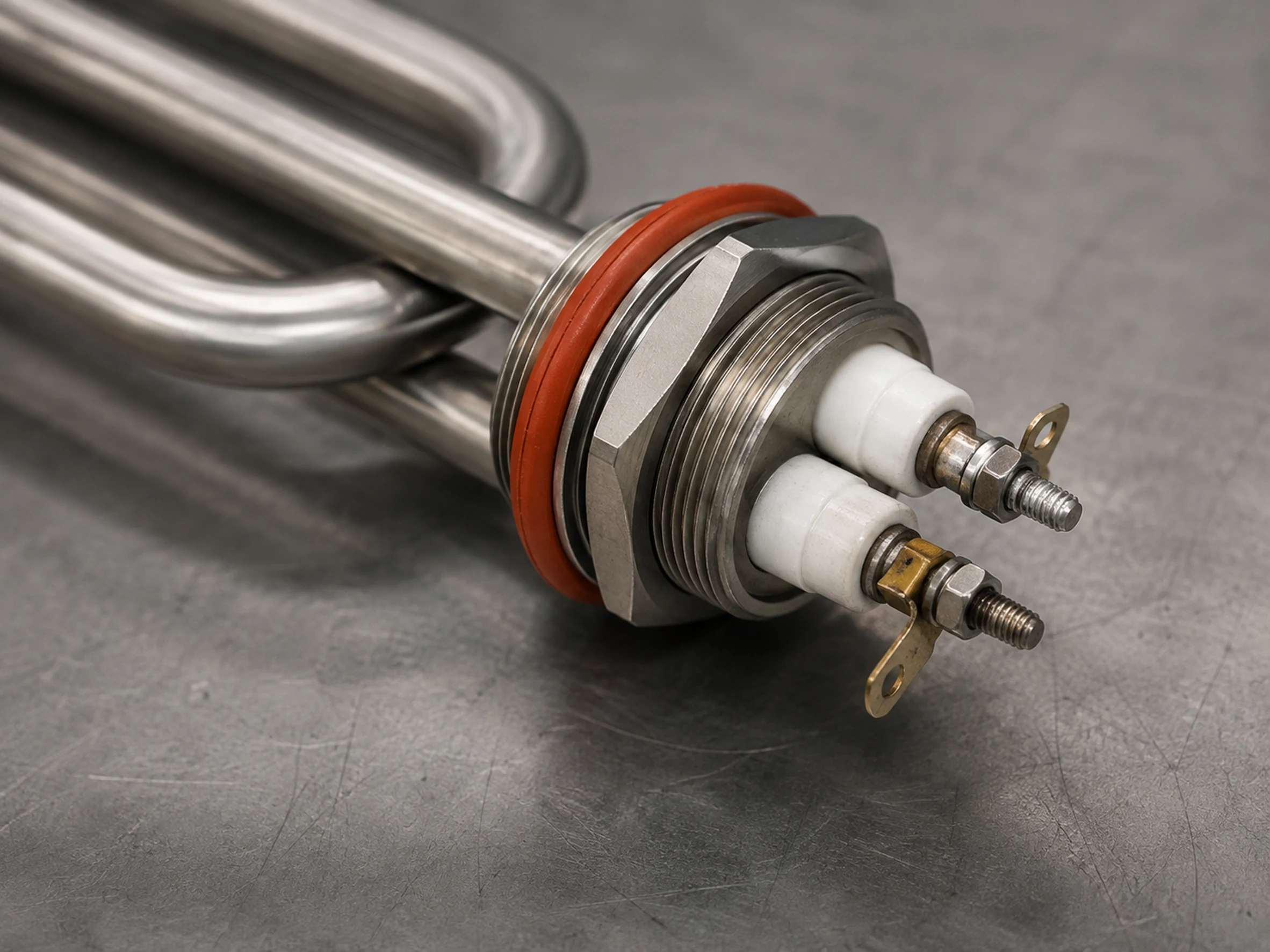
A typical element includes two parallel sheathed legs, a formed U bend, internal resistance coil, magnesium-oxide insulation, cold pins, terminals or leads and optional threaded fittings or brackets.
The design must consider leg length, center distance, bend radius, immersion depth, heat-transfer condition and terminal location. For liquid service, the heated section must remain immersed; for air service, the required airflow must be maintained.
Unlike the broader Tubular Heating Element range, this page focuses specifically on double-ended U-shaped elements. Key selection dimensions include tube diameter, leg length, center distance, bend radius, heated length, cold zones, mounting dimensions and terminal orientation.
Xiangyuan Machinery can manufacture U-shaped elements according to drawings and can assemble multiple elements into flanged immersion bundles or air-heating assemblies.
Key Features
Compact U-Shaped Geometry
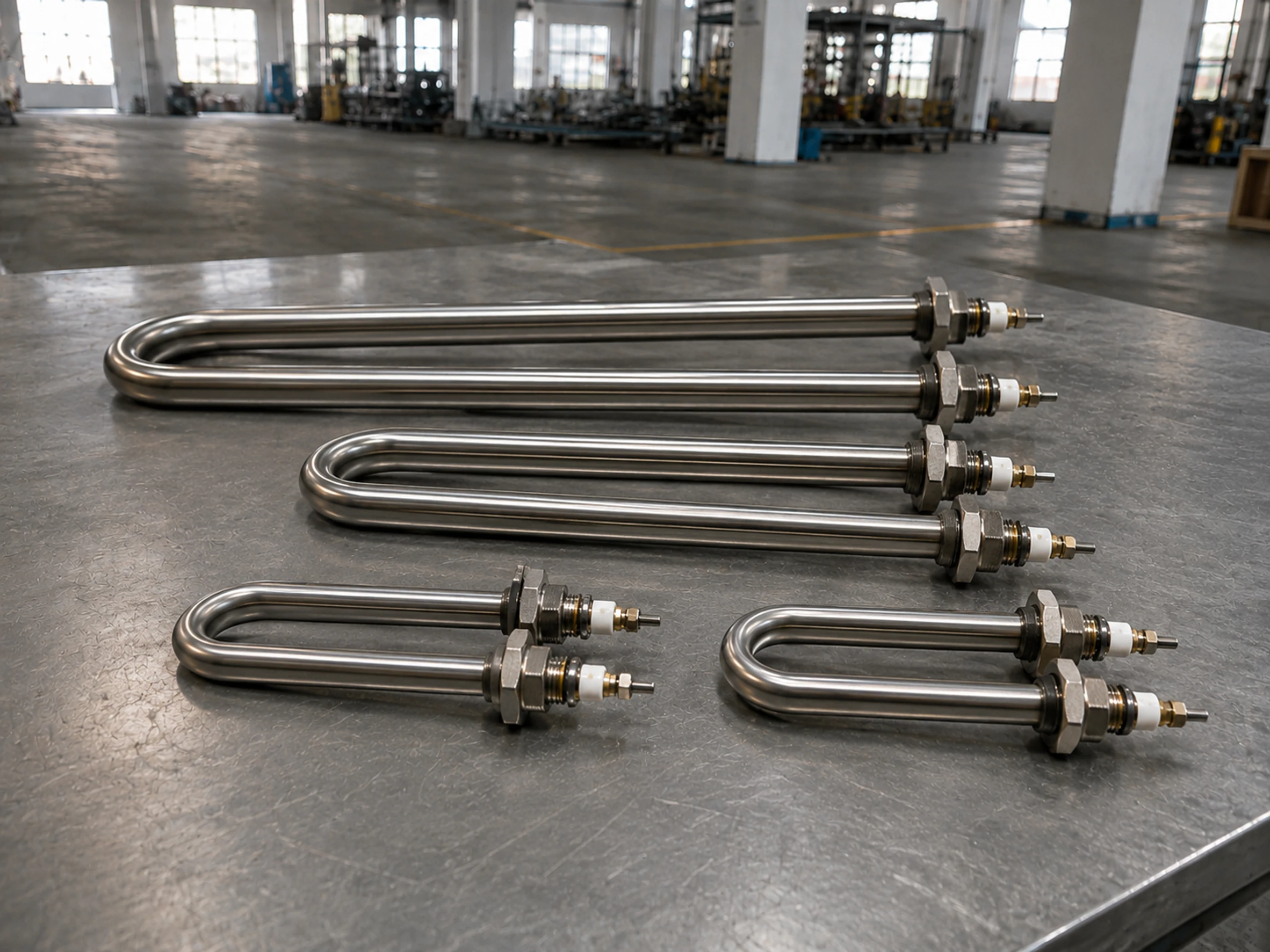
Two parallel legs provide a compact heating arrangement with one mounting side.
Custom Leg Length
Heated and cold lengths can be adjusted to the tank, duct or equipment layout.
Custom Center Distance
Spacing between the two legs can be manufactured from the installation drawing.
Multiple Heating Media
Designs are available for water, oil, air and compatible industrial media.
Sheath Material Options
SS304, SS316L, SS310S, Incoloy 800, Incoloy 840 and selected alloys are available.
Controlled Watt Density
Surface loading is selected from medium, temperature, flow and fouling risk.
Fitting and Bracket Options
Threaded fittings, mounting plates, flanges and support brackets can be added.
Terminal Options
Studs, pins, flexible leads and protected terminal arrangements can be supplied.
Bundle Assembly Available
Multiple U-shaped elements can be assembled into a flanged or equipment-specific heater.
Typical Technical Parameters
The following parameters are for reference only. Final design is confirmed according to the heating medium, operating temperature, tube diameter, leg length, center distance, bend radius, allowable watt density, mounting method, electrical supply and project requirements.
| Parameter | Customizable Range or Options |
|---|---|
| Product Name | U-Shaped Tubular Heating Element |
| Heating Medium | Water, oil, air or compatible process medium |
| Tube Diameter | Customized according to forming requirements and minimum bend radius |
| Leg Length | Customized overall, heated and cold lengths |
| Center Distance | Customized according to installation drawing |
| Bend Radius | Selected according to tube diameter and material |
| Heating Power | Customized according to supply voltage, heated length, allowable watt density and required heating duty |
| Voltage | Customized according to element dimensions, power and project electrical supply |
| Watt Density | Selected according to medium and heat transfer |
| Sheath Material | SS304, SS316L, SS310S, Incoloy 800, Incoloy 840 or selected alloy |
| Mounting | Threaded fitting, flange, bracket, compression fitting or custom |
| Terminal / Lead | Stud, pin, flexible lead or custom connection |
| Cold Zone | Customized near terminals and fittings |
| Sensor Option | Thermocouple or separate sensor where suitable |
| Optional Design | Standard U-shape, narrow U-shape, elongated U-shape, multi-pass U-shaped element, multiple-element bundle, flange-mounted or bracket-mounted assembly |
Structure, Materials, Control and Safety
Structure of the Heater
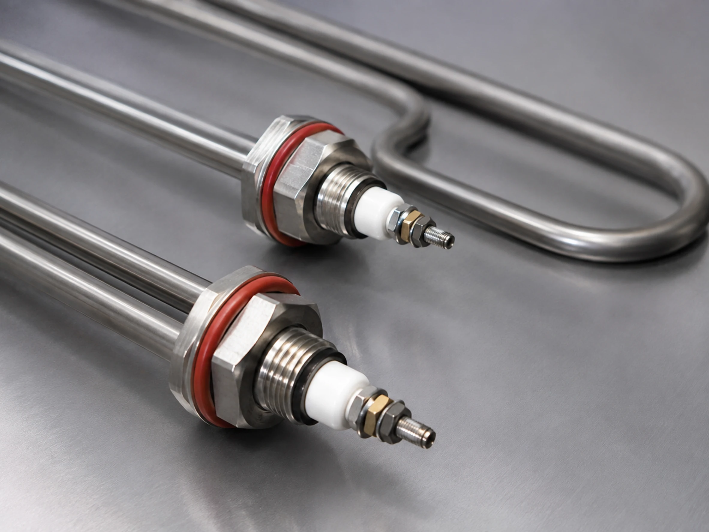
The element contains a resistance coil and compacted magnesium oxide inside a metal sheath. After manufacture and annealing, the tube is bent into a U shape with the required leg length, center distance and bend radius.
The two terminal legs contain cold sections that pass through fittings, brackets or a flange. The terminal ends can use threaded studs, pins, lead wires, ceramic insulators or protected enclosures.
Multiple U-shaped elements can be arranged in parallel and welded or brazed to a flange or support plate to form a larger heater assembly.
Materials and Customization
Sheath material is selected according to the heating medium, operating temperature, corrosion, oxidation and required service conditions.
Fittings, flanges, brackets, terminals and seals should be compatible with the sheath material and process environment.
Leg length, center distance, cold zones, mounting, terminal direction, surface treatment and bundle arrangement can be customized.
Control System
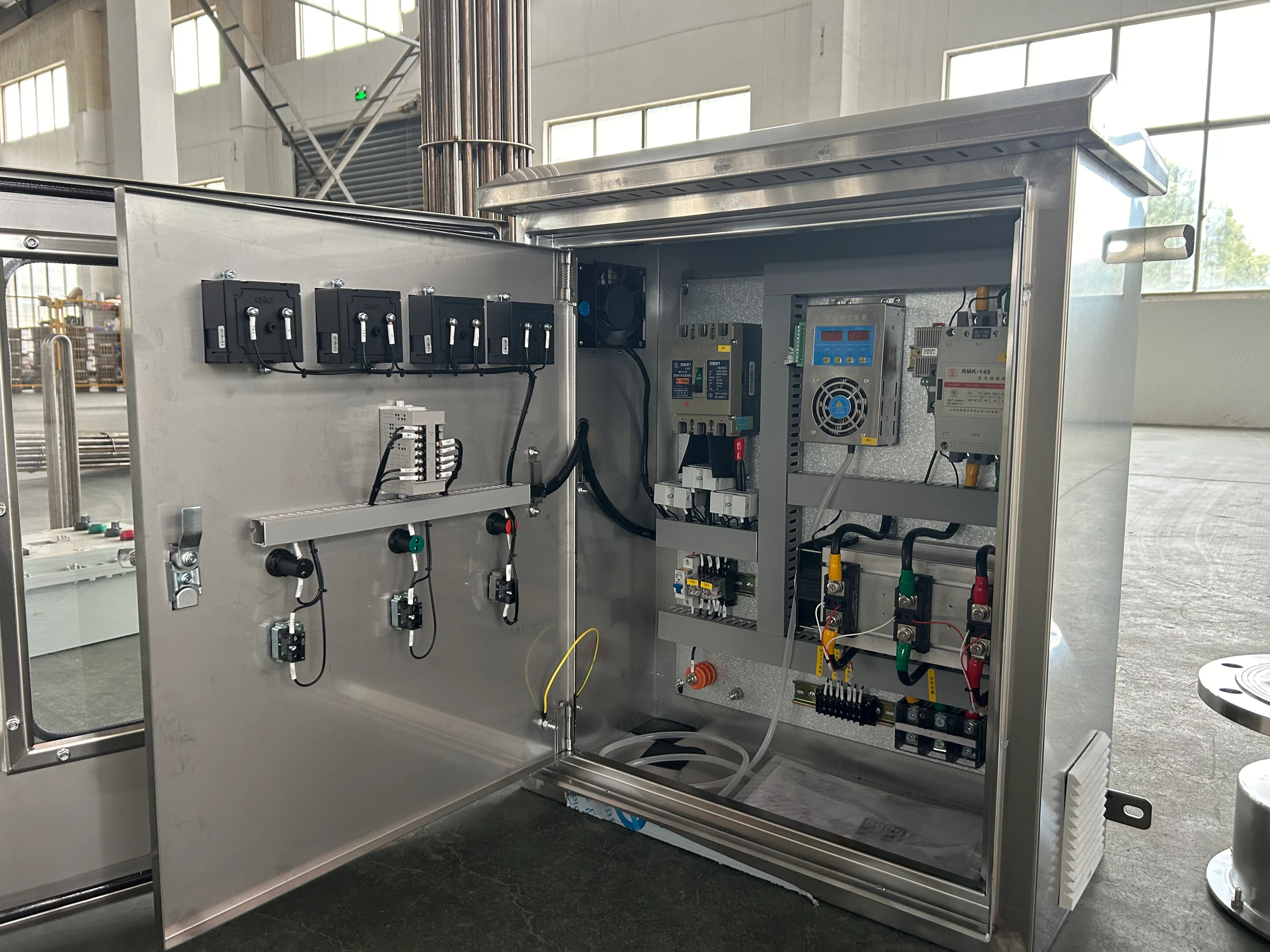
U-shaped elements are normally controlled by an external temperature controller. PID control with contactor, SSR or SCR switching can be used according to total power and required stability.
For liquid immersion, the controller should work with liquid-level or flow protection and an independent over-temperature limit. For air heating, fan or airflow interlocks should be included where required.
Multiple elements can be connected in stages or zones and integrated with a PLC or equipment control panel.
Safety Protection
The heated section of a liquid-heating U element must remain immersed during operation. Dry operation can produce excessive sheath temperature.
For air heating, element watt density and airflow must be matched. Terminals and cold zones should remain outside the highest-temperature area and be protected from moisture and mechanical damage.
Grounding, insulation-resistance testing, earth-leakage protection, an independent over-temperature cutout and appropriate process interlocks should be included in the final equipment design.
Typical Applications
Water Tanks
Direct immersion heating in industrial water tanks and vessels.
Oil Tanks
Heating compatible oils with selected watt density.
Process Vessels
Installing through threaded fittings, brackets or flanges.
Air Ducts and Ovens
Heating moving air in ducts, ovens and dryers.
Industrial Water-Heating Equipment
Heating water in compatible tanks and process equipment.
Cleaning Equipment
Heating wash or rinse liquid in industrial machines.
Marine Equipment
Heating water or oil in marine utility systems.
Chemical Equipment
Heating compatible liquids with selected corrosion-resistant materials.
Food Machinery
Heating compatible equipment where hygiene requirements are separately confirmed.
Drying Equipment
Providing heat in hot-air and circulation systems.
Custom Machines
Integrating a compact U element into industrial equipment.
Flanged Heater Bundles
Combining multiple U-shaped elements on a common flange.
How to Select the Right U-Shaped Tubular Heating Element
1. Heating Medium
State water, oil, air or other medium.
2. Operating Temperature
Provide normal and maximum temperature.
3. Voltage
Provide the operating voltage, phase, frequency and wiring connection method.
4. Power
Provide total power or required watt density.
5. Tube Diameter
State required tube diameter.
6. Leg Length
Provide overall, heated and cold lengths.
7. Center Distance
Provide spacing between the two legs.
8. Bend Radius
Provide drawing or available installation space.
9. Immersion or Airflow Condition
Describe liquid level, flow or air velocity.
10. Sheath Material
State corrosion and temperature requirements.
11. Mounting Method
Specify fitting, flange, bracket or support plate.
12. Terminal or Lead
Specify type, length and direction.
13. Sensor Option
Confirm thermocouple or external sensor.
14. Control and Protection
Provide controller and interlock requirements.
15. Drawing and Quantity
Supply tolerances, quantity and testing requirements.
Frequently Asked Questions
Common questions about U-Shaped Tubular Heating Element selection, customization and industrial use.
What is a U-Shaped Tubular Heating Element?
What dimensions are required for customization?
Can it be used in both liquid and air?
Can multiple U-shaped elements be assembled on a flange?
Can sensors and control equipment be supplied?
Related Heating Solutions
For straight and other formed electric resistance element designs, see Tubular Heating Element . For U-shaped or formed elements with fins for forced-air heating, see Finned Tubular Heating Element . For multiple tubular elements assembled on a flange for liquid immersion heating, see Flanged Immersion Heater . For simpler stainless steel rod-style electric heating elements, see Stainless Steel Electric Heater Rod .
Why Choose Xiangyuan Machinery
Xiangyuan Machinery manufactures U-shaped tubular heating elements from the customer’s medium, leg dimensions, watt density, mounting and terminal requirements.
Thermal & Material Engineering
Customized leg length, center distance and bend radius. Multiple sheath materials and watt-density options.
Flexible Mechanical Arrangement
Threaded, flanged, bracket and custom mounting.
Control & Safety Integration
Terminal, lead, cold-zone and sensor customization. Individual elements or multiple-element bundles.
Complete Project Supply
Compatible control and protection solutions. Electrical, dimensional and insulation testing according to order scope.
Send Us Your U-Shaped Element Drawing
Provide medium, tube diameter, leg length, center distance, voltage, power, watt density, sheath, mounting, cold zones, terminals, sensor and quantity. Xiangyuan Machinery will prepare a confirmed specification and quotation.