

CUSTOM OILFIELD ELECTRIC HEATING SYSTEM
Deep Well Heater
Custom downhole electric heating equipment for heavy-oil wells, wellbore heating, viscosity reduction and production-support applications.
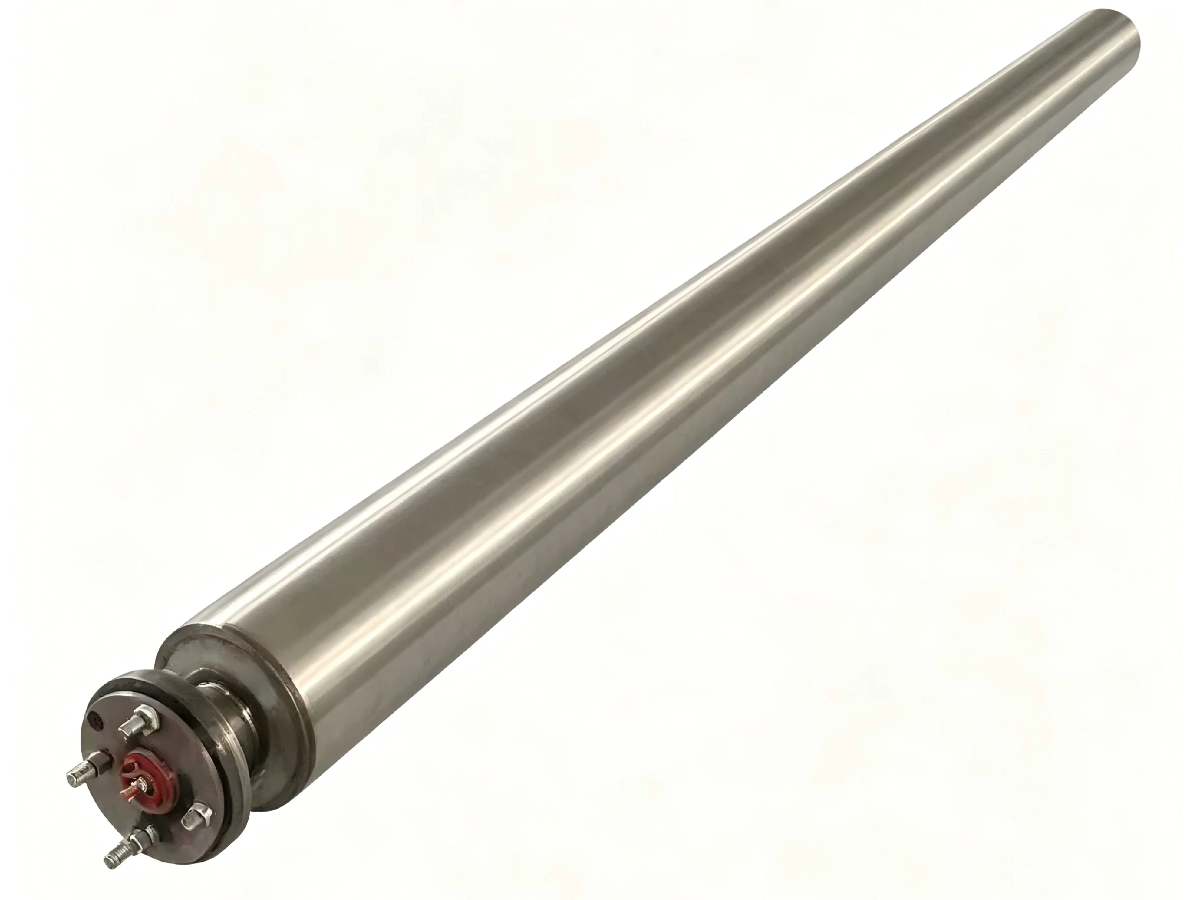
The Deep Well Heater is a custom electric heating device installed in the wellbore to provide heat near the downhole fluid or selected production interval. It can be used to support heavy-oil flow, reduce local viscosity, mitigate wax-related flow restrictions and assist low-temperature startup where the well conditions are suitable.
Heating power, installation depth, heating length, outside diameter, sheath material, power cable, wellhead feedthrough, surface control cabinet and protection functions are engineered from the well data. The final solution must be confirmed from casing or tubing size, depth, pressure, temperature, fluid composition and completion arrangement.
Product Overview
The Deep Well Heater is an oilfield electric heating solution intended for installation in the wellbore rather than in an above-ground pipeline. It supplies heat directly or near the downhole fluid path according to the selected installation and completion method.
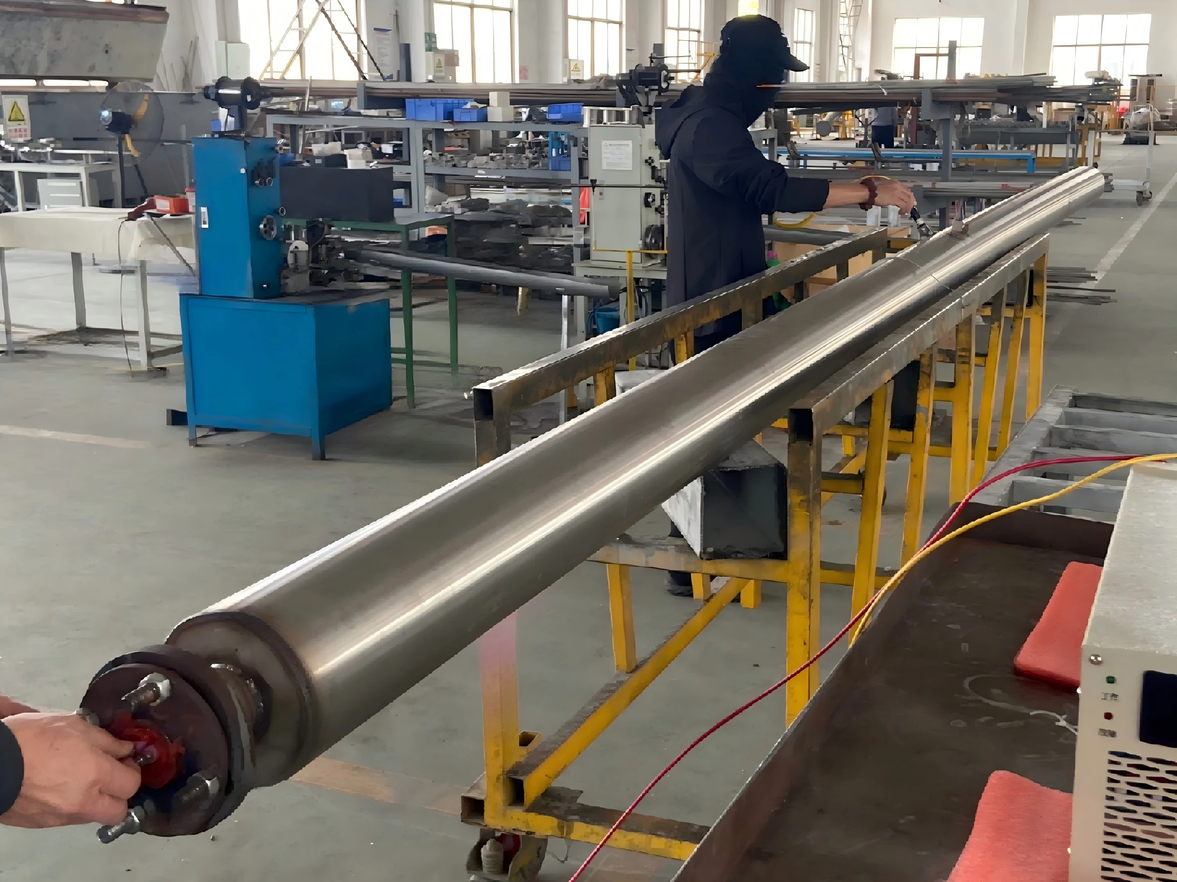
A typical system can include a downhole heating section, protective outer structure, power cable, cable connection and sealing components, wellhead feedthrough, surface junction box, temperature sensors and control cabinet. Centralizers, supports and installation tools can be included according to the well structure.
The heater should be engineered from well depth, casing or tubing internal diameter, fluid properties, pressure, temperature, corrosive components, required heating length and available surface power. A standard product size cannot be selected without these inputs.
Xiangyuan Machinery can supply the downhole heater and surface control equipment, and can coordinate the electrical and mechanical interface with the customer’s wellhead and installation plan.
Key Features
Well-Specific Engineering
Outside diameter, heating length, power and installation depth are designed from the well data.
Downhole Heating Section
The heating section provides localized wellbore or fluid heating at the selected depth.
Heavy-Oil Application
The design can support viscosity reduction and flow improvement in suitable heavy-oil wells.
Cable and Feedthrough Integration
Power cable and wellhead electrical feedthrough are included in the interface design.
Pressure and Temperature Consideration
Downhole pressure, fluid temperature and installation environment are design inputs.
Corrosion-Resistant Material Options
Sheath and structural materials can be selected from fluid composition and temperature.
Surface Control Cabinet
Current, voltage, power and temperature monitoring can be integrated above ground.
Electrical Protection
Insulation, leakage, overcurrent, grounding and over-temperature functions can be included.
Customized System Scope
Supply can include heater, cable, wellhead interface, controls and installation-related components.
Typical Technical Parameters
The following parameters are for reference only. Final design is confirmed according to well depth, casing or tubing dimensions, heated interval, fluid properties, downhole pressure and temperature, available power, cable route, wellhead interface and project requirements.
| Parameter | Customizable Range or Options |
|---|---|
| Product Name | Deep Well Heater |
| Application Medium | Heavy oil, crude oil, produced fluids or other confirmed downhole media |
| Heating Power | Customized according to required heat input and well conditions |
| Installation Depth | Engineered according to target interval and well completion |
| Heating Length | Customized according to the required heated section |
| Outside Diameter | Selected from casing or tubing internal diameter and clearance |
| Downhole Pressure | According to well operating and design conditions |
| Downhole Temperature | According to formation, fluid and operating conditions |
| Power Cable Length | Customized according to installation depth and surface routing |
| Heater Sheath / Outer Structure Material | Stainless steel or selected corrosion-resistant alloys according to temperature, pressure, fluid composition and service conditions |
| Wellhead Interface | Customized feedthrough, sealing and connection arrangement |
| Power Supply | Customized voltage, phase and frequency according to site capacity and heater design requirements |
| Control Method | Surface control cabinet, staged control, SCR or PLC where applicable |
| Monitoring | Current, voltage, power, insulation-resistance and temperature monitoring options |
| Protection Options | Overcurrent and short-circuit protection, earth-leakage protection, insulation-resistance monitoring, phase-loss and phase-sequence protection where applicable, grounding, over-temperature protection and emergency stop |
| Optional Supply | Cable, junction box, wellhead feedthrough, centralizers, controls and surface package |
Structure, Materials, Control and Safety
Structure of the Heater
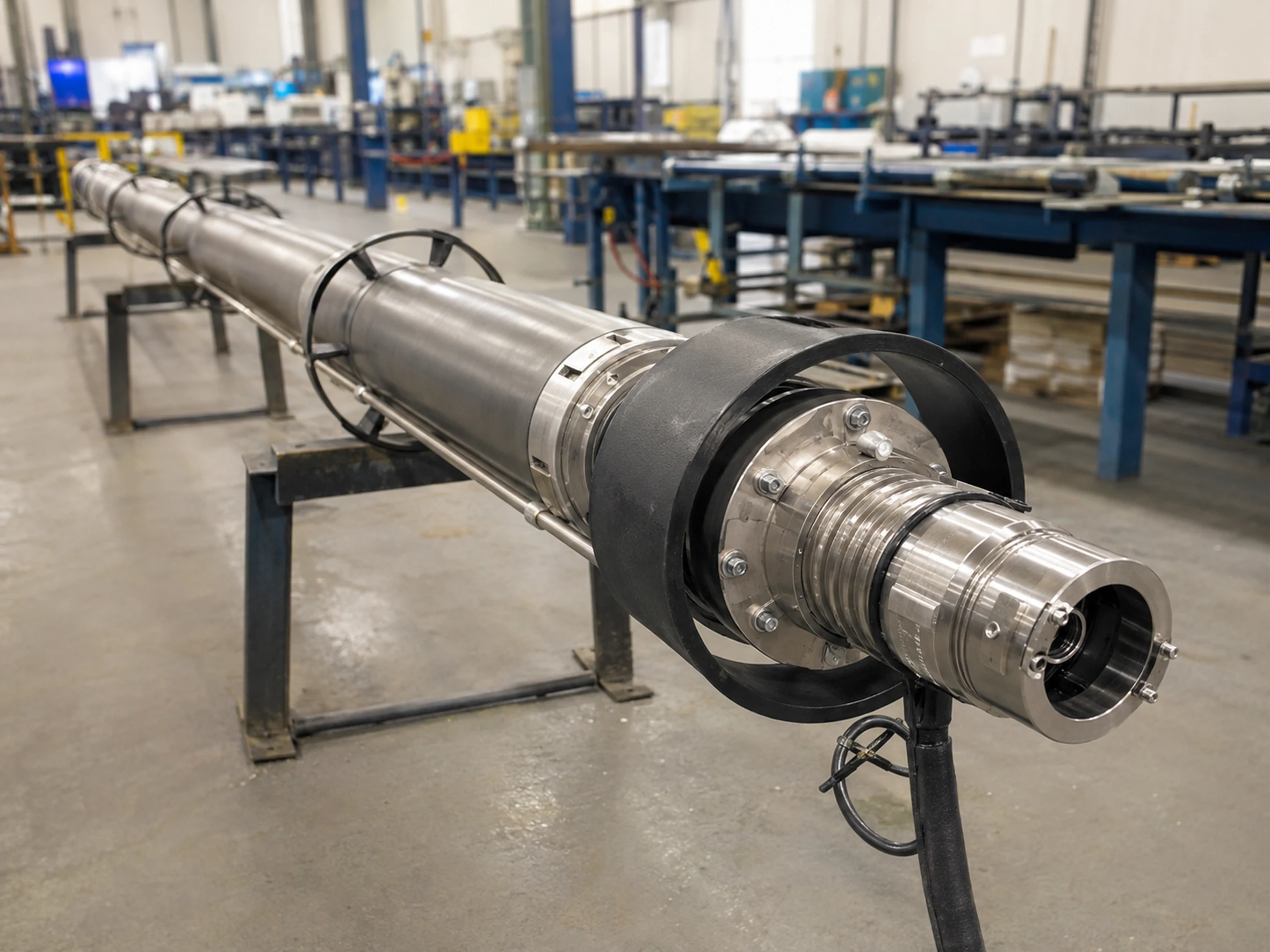
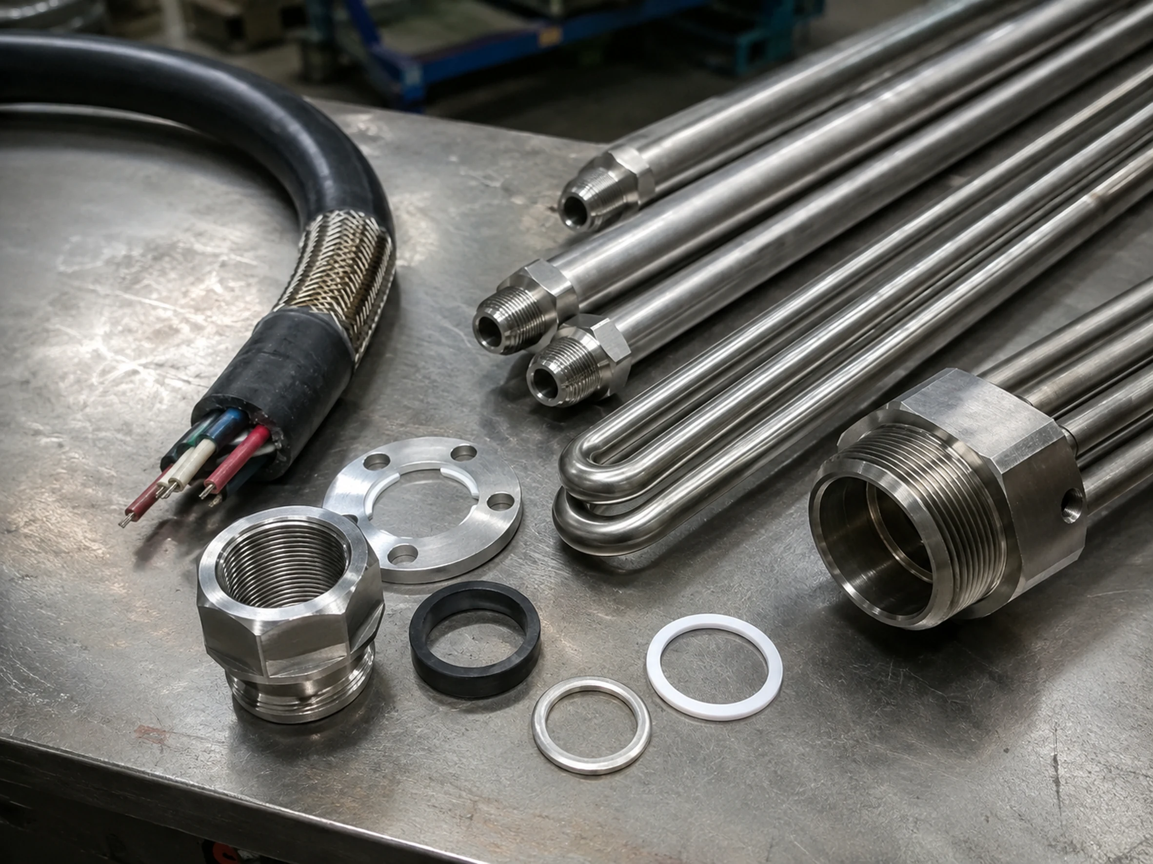
The system normally includes a downhole heating section with a protective metal sheath or outer structure, an internal resistance-heating assembly, electrical connection and a power cable extending to the surface. The outside diameter and heating length are selected to fit the wellbore and provide the required heated interval.
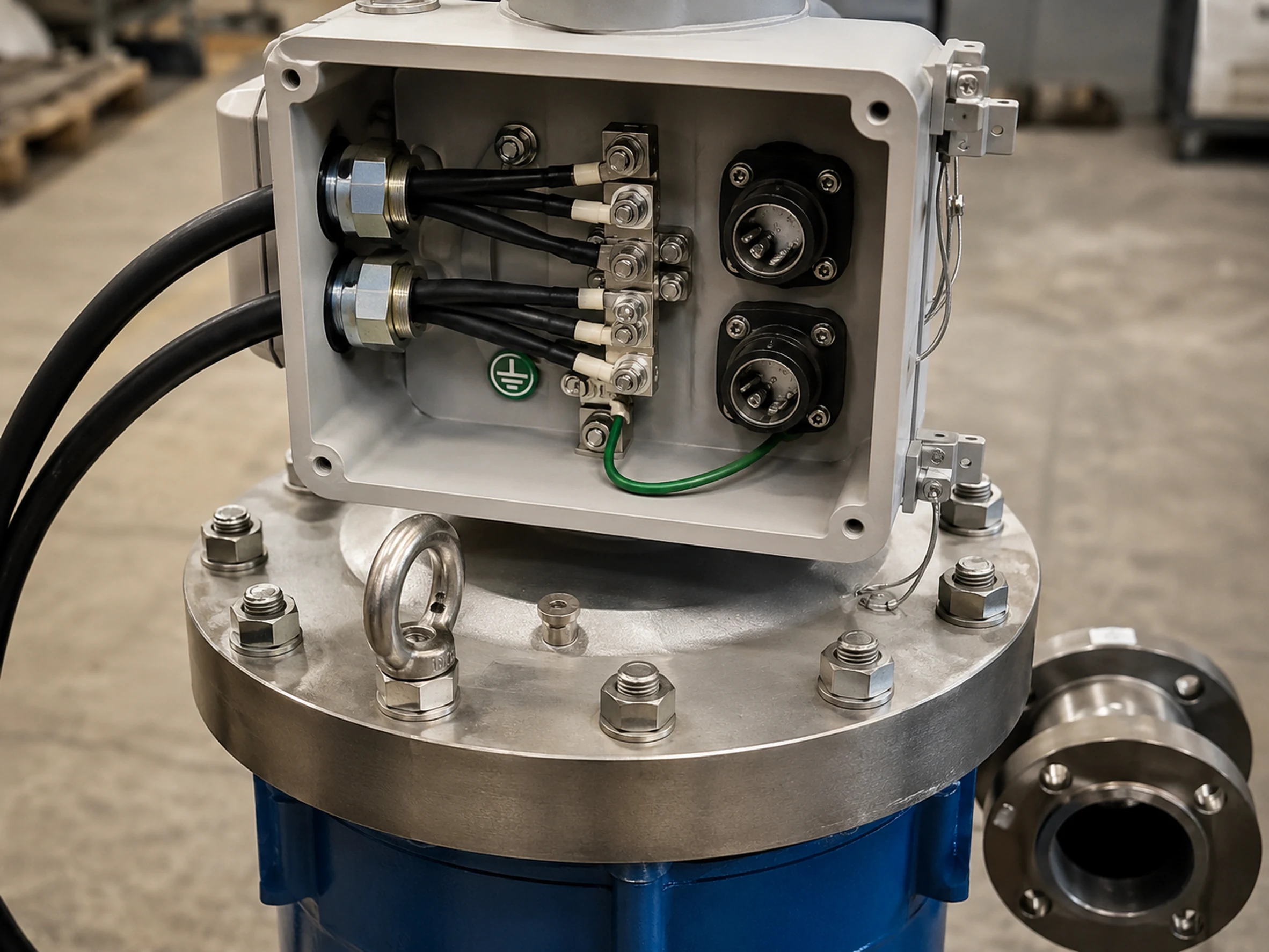
A wellhead feedthrough and sealing arrangement are required to pass electrical power through the wellhead while matching the completion and pressure requirements. Surface components can include a junction box, cable protection, control cabinet and temperature or electrical monitoring devices.
Centralizers, support components and installation tools may be included according to the well geometry. The final structure must be reviewed together with the customer’s wellhead, tubing, casing and installation procedure.
Materials and Customization
Material selection depends on downhole temperature, pressure, water cut, salinity, sulfur compounds, chlorides and other corrosive components. Stainless steel or selected corrosion-resistant alloys can be evaluated for the heater sheath and structural components.
Cable insulation, seals, connectors and wellhead feedthrough materials must also match the temperature, pressure and fluid environment. The surface equipment should be selected for outdoor oilfield conditions and the confirmed area classification.
Heating length, outside diameter, cable length, connector arrangement, sensor locations and surface package can be customized from the well data.
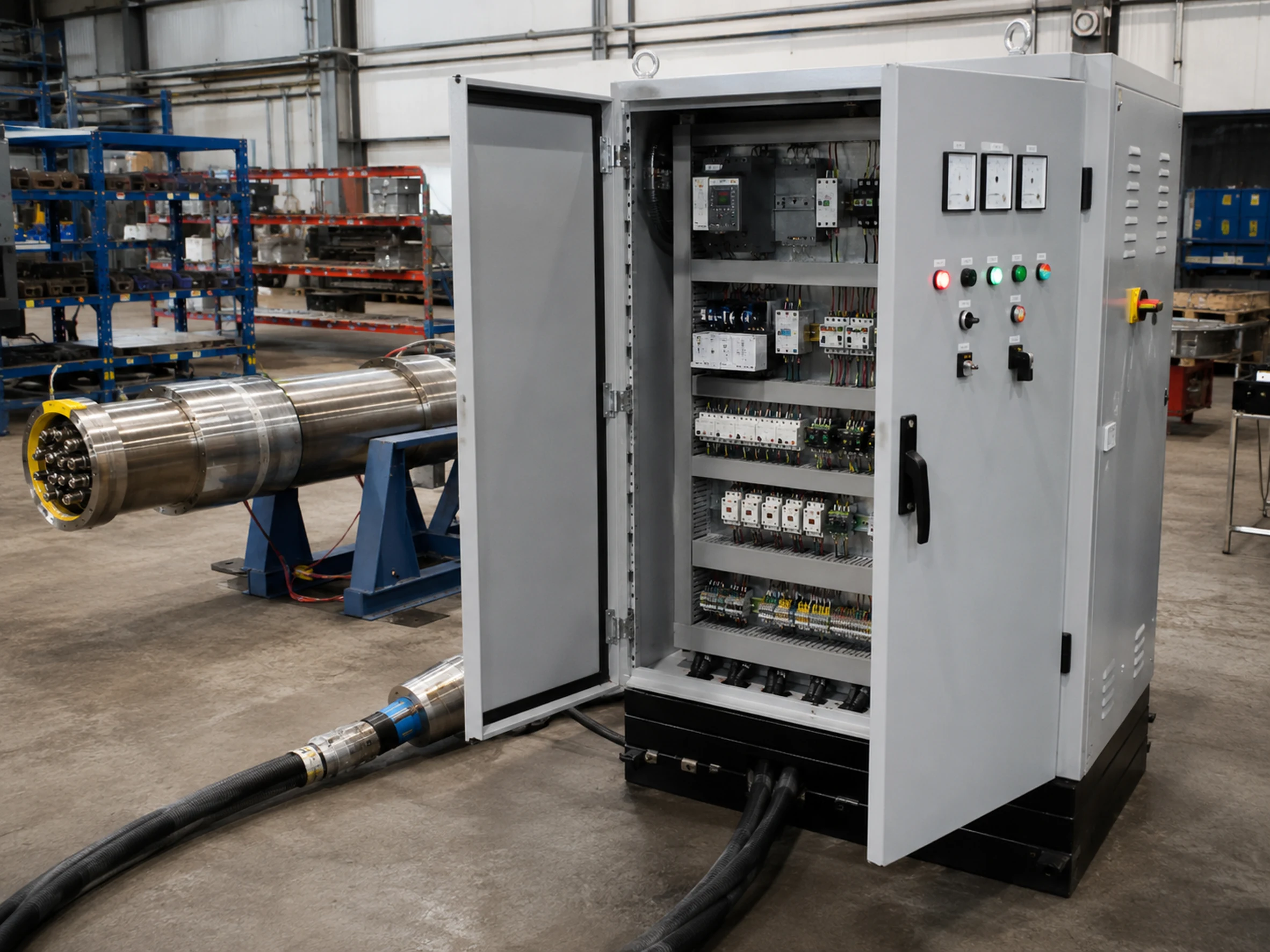
Control System
The Deep Well Heater is normally operated from a surface control cabinet. Control options can include staged power, SCR regulation, PLC control, local/remote operation and HMI display.
Electrical monitoring can include voltage, current, power, insulation resistance, earth leakage and operating status.
The control system can provide startup sequencing, alarm, trip, remote status and data interface according to the oilfield operating requirements.
Safety Protection
Typical protection includes overcurrent and short-circuit protection, earth-leakage protection, insulation-resistance monitoring, phase-loss and phase-sequence protection where applicable, grounding, over-temperature protection and emergency stop. Cable mechanical protection and connection sealing are also important parts of the system design.
The heater installation must be compatible with the wellhead, tubing, casing, pressure and completion method. Installation depth, clearances and retrieval requirements should be verified before manufacture.
For hazardous-area applications, relevant explosion-proof products can be supplied with Chinese explosion-proof certification, with the marking Ex db IIC T1–T6 Gb. The final configuration is selected according to the confirmed area classification, temperature class and project requirements. Certification requirements for export projects should be confirmed according to the destination market.
Typical Applications
Heavy-Oil Wells
Providing downhole heat to support the flow of high-viscosity crude.
Wellbore Heating
Raising temperature in a selected wellbore interval.
Viscosity Reduction
Reducing local fluid viscosity when temperature response is suitable.
Wax and Paraffin Control
Supporting mitigation of temperature-related wax restrictions in selected wells.
Cold-Weather Startup
Assisting well startup under low ambient and fluid-temperature conditions.
Production Support
Providing supplemental heat where thermal input can improve operating stability.
Pilot Projects
Testing electrical downhole heating before wider field application.
Marginal-Well Evaluation
Evaluating heat-assisted production for selected low-rate wells.
Heavy-Oil Recovery Support
Supplementing other production methods where engineering review supports the use.
Well Intervention Support
Temporary or project-specific heating during selected operations.
Research and Demonstration Wells
Providing controlled downhole heat for technical studies.
Customized Oilfield Systems
Integrating downhole heating with surface controls and monitoring.
How to Select the Right Deep Well Heater
1. Well Type
Provide production, test, injection or other well type.
2. Casing and Tubing Data
Provide internal diameters, grades and completion drawing.
3. Installation Depth
State target depth and heated interval.
4. Fluid Properties
Provide viscosity-temperature data, water cut, gas content, solids, salinity, chlorides, sulfur compounds and other corrosive components.
5. Downhole Pressure
Provide normal, maximum and design pressure.
6. Downhole Temperature
Provide formation and operating temperature.
7. Required Heat Input
State the target temperature increase, required heated interval, desired viscosity reduction or available thermal model.
8. Available Power
Provide voltage, phase, frequency and site capacity.
9. Cable Route
Provide wellhead-to-cabinet distance and surface routing.
10. Wellhead Interface
Provide feedthrough, sealing and flange requirements.
11. Installation and Retrieval
Describe running method, supports and retrieval needs.
12. Material Requirement
Provide corrosion and alloy requirements.
13. Monitoring
State temperature and electrical monitoring needs.
14. Control and Communication
Confirm local, remote, PLC, HMI or DCS requirements.
15. Site Classification
Provide outdoor conditions, IP and hazardous-area classification.
Frequently Asked Questions
Common questions about Deep Well Heater selection, customization and industrial use.
What is a Deep Well Heater?
What information is needed before design?
Can it be used for heavy oil?
What does the supply scope include?
Can explosion-proof surface equipment be provided?
Related Heating Solutions
For above-ground wellhead and gathering-station heating, see Oilfield Electric Heating System. For crude-oil pipeline heating, see Electric Crude Oil Heater. For a modular surface package, see Skid-Mounted Electric Heating System.
Why Choose Xiangyuan Machinery
Xiangyuan Machinery develops deep-well heating equipment as a well-specific engineering project using mechanical, electrical, thermal and oilfield interface data.
1. Well Type
Provide production, test, injection or other well type.
2. Casing and Tubing Data
Provide internal diameters, grades and completion drawing.
3. Installation Depth
State target depth and heated interval.
4. Fluid Properties
Provide viscosity-temperature data, water cut, gas content, solids, salinity, chlorides, sulfur compounds and other corrosive components.
5. Downhole Pressure
Provide normal, maximum and design pressure.
6. Downhole Temperature
Provide formation and operating temperature.
7. Required Heat Input
State the target temperature increase, required heated interval, desired viscosity reduction or available thermal model.
8. Available Power
Provide voltage, phase, frequency and site capacity.
9. Cable Route
Provide wellhead-to-cabinet distance and surface routing.
10. Wellhead Interface
Provide feedthrough, sealing and flange requirements.
11. Installation and Retrieval
Describe running method, supports and retrieval needs.
12. Material Requirement
Provide corrosion and alloy requirements.
13. Monitoring
State temperature and electrical monitoring needs.
14. Control and Communication
Confirm local, remote, PLC, HMI or DCS requirements.
15. Site Classification
Provide outdoor conditions, IP and hazardous-area classification.
Frequently Asked Questions
Common questions about Deep Well Heater selection, customization and industrial use.
What is a Deep Well Heater?
What information is needed before design?
Can it be used for heavy oil?
What does the supply scope include?
Can explosion-proof surface equipment be provided?
Is a Deep Well Heater the same as a downhole electric heater?
Related Heating Solutions
For above-ground wellhead and gathering-station heating, see Oilfield Electric Heating System . For crude-oil pipeline heating, see Electric Crude Oil Heater. For a modular surface package, see Skid-Mounted Electric Heating System .